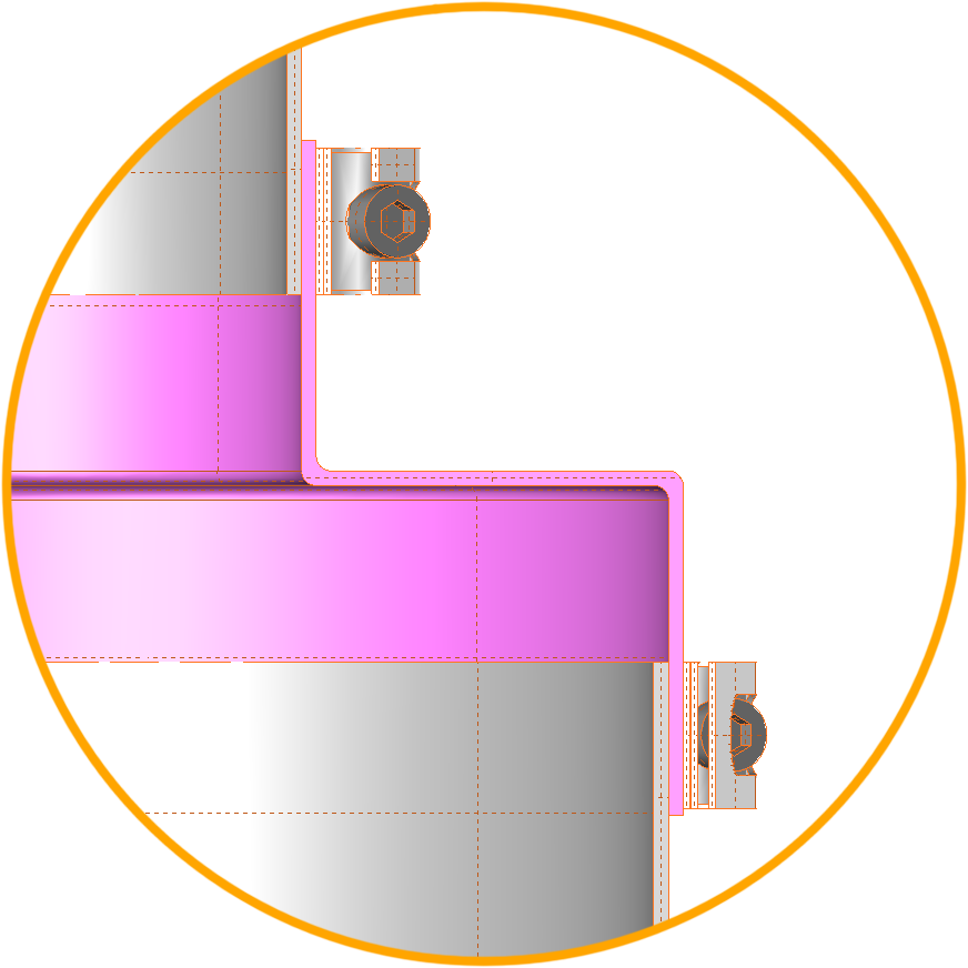
Features
- Wide range of standard diameters
- Large diameter range
- Fits Imperial and Metric tubing
- Low influence on Weighing process
- Offset / misalignment
- Rectangular to round
- Antistatic version available
- Seamless
- Fast delivery of custom design
- Low tooling cost for special designs
Step Bellows
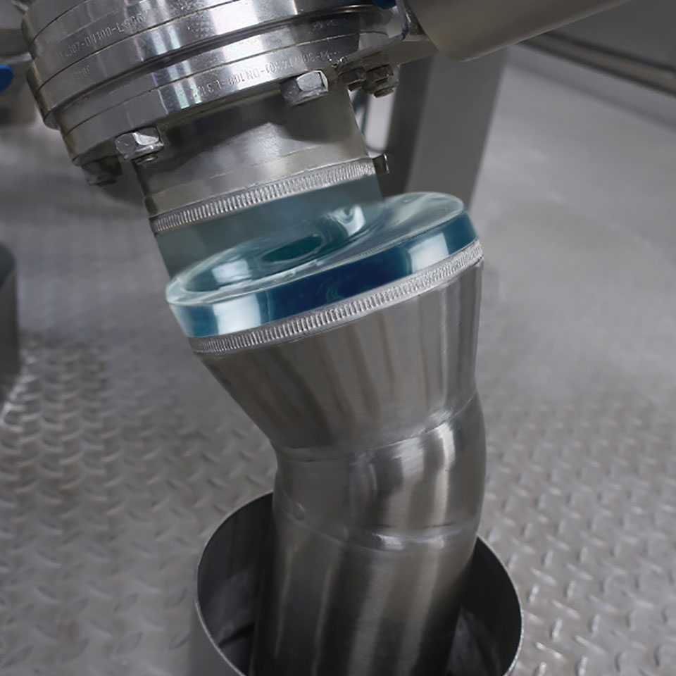
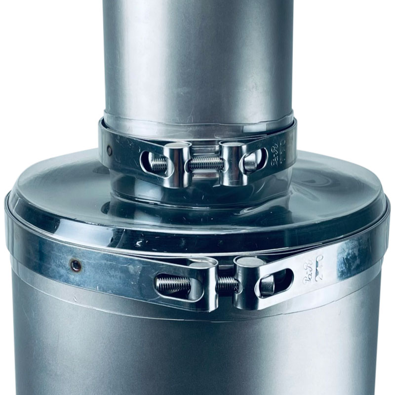
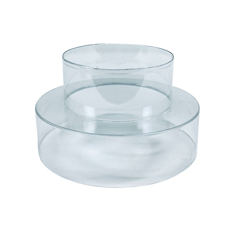
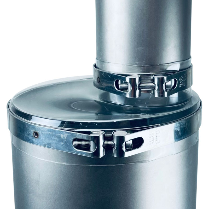
Seamless Step bellows are for the flexible connection of mixers, feeders or vessels on weighing and loading cells to supply lines, drain pipes or other forms of air transport or powder transport with two different dimensions of tubing. Flexible connectors with two different diameters are more flexible than straight cylindrical sleeves. This makes them ideal for weighing or dosing equipment.
Step bellows and conical reducers are available in several materials, such as; Silicone, Polyurethane and even flexible PVC. Conical- and Step Bellows are now available in many shapes and sizes. These bellows have no seams, which makes them more hygienic. The bellows can be designed as offset if the pipes are not aligned.
Advantages
- Air-tight
- Dust-tight
- No pile up
- Low adjustment force and extremely flexible
- Food contact safety
- Dimensions custom made
- Hygienic design
- Two different diameters
- No convolution in the design
- No welding, no glue
- Made in 1 single piece
Materials
The Step Bellow can be produced in various materials. For more information please go to our Materials Comparison Table.
- Thermoplastic
- Explosion Safe Poly Urethane with ATEX declaration
- Materials;
- Poly Urethane Transparent
- Mipolan PVC honey Yellow
- PVC transparent
- Seamless diameter 60 – 350mm
- Larger than diameter 350mm welded from several parts
- Conical shape
- Flat reducer shape
- Bellow shapes
- Offset / misalignment
- Side branches / side connection
- Low quantities upward from 1 pcs
- Many standard tools cost free
- Low tool costs
Silicone white / translucent / black antistatic
- Production to your design upward from 50pcs
- Tooling cost are higher
- Only available as casted product
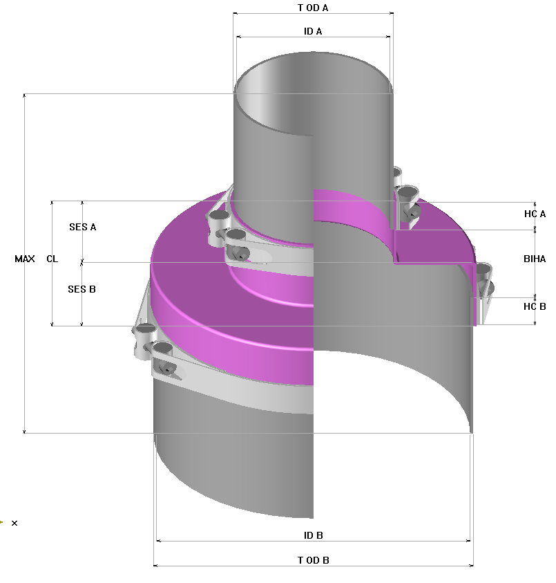
| Parameter | Explanation |
| T OD A | Tube Outside Diameters |
| ID A | Inside Diameter |
| HC A | Hose Clamp Width |
| SES A | Straight End Sleeve |
| CL | Length Weighing Bellow |
| BIHA | Length Between Tubes / Flanges |
| MAX | Maximum Available Build in Height |
| SES B | Straight End Sleeve |
| HC B | Hose Clamp Width |
| OD B | Inside Diameter |
| T OD B | Tube Outside Diameter |
| Diameters | Length Straight End Sleeve ( R ) |
||||
| (mm) | (Inch) | range | |||
| 10 | 0,39 | 10 | – | 12 | 20 |
| 13 | 0,51 | 13 | – | 15 | 20 |
| 17 | 0,67 | 17 | – | 19 | 20 |
| 21 | 0,83 | 21 | – | 23 | 15 |
| 21 | 0,83 | 21 | – | 23 | 20 |
| 25 | 0,98 | 25 | – | 27 | 20 |
| 27 | 1,06 | 27 | – | 30 | 20 |
| 27 | 1,06 | 27 | – | 30 | 25 |
| 30 | 1,18 | 30 | – | 32 | 20 |
| 33 | 1,30 | 33 | – | 35 | 20 |
| 33 | 1,30 | 33 | 35 | 25 | |
| 38 | 1,50 | 38 | – | 41 | 20 |
| 41 | 1,61 | 41 | – | 45 | 20 |
| 48 | 1,89 | 48 | – | 52 | 40 |
| 60 | 2,36 | 60 | – | 64 | 15 |
| 60 | 2,36 | 60 | – | 64 | 40 |
| 65 | 2,56 | 65 | – | 69 | 40 |
| 73 | 2,87 | 73 | – | 77 | 40 |
| 76 | 2,99 | 76 | – | 80 | 40 |
| 80 | 3,15 | 80 | – | 84 | 40 |
| 85 | 3,35 | 85 | – | 88 | 40 |
| 88 | 3,46 | 88 | – | 92 | 40 |
| 95 | 3,74 | 95 | – | 99 | 40 |
| 99 | 3,90 | 99 | – | 104 | 40 |
| 104 | 4,09 | 104 | – | 108 | 25 |
| 105 | 4,13 | 105 | – | 109 | 40 |
| 109 | 4,29 | 109 | – | 113 | 40 |
| 114 | 4,49 | 114 | – | 120 | 40 |
| 116 | 4,57 | 116 | – | 122 | 40 |
| 120 | 4,72 | 120 | – | 125 | 40 |
| 126 | 4,96 | 126 | – | 131 | 40 |
| 129 | 5,08 | 129 | – | 135 | 40 |
| 139 | 5,47 | 139 | – | 144 | 40 |
| 150 | 5,91 | 150 | – | 156 | 40 |
| 156 | 6,14 | 156 | – | 160 | 40 |
| 162 | 6,38 | 162 | – | 166 | 40 |
| 168 | 6,61 | 168 | – | 175 | 25 |
| 168 | 6,61 | 168 | – | 175 | 40 |
| 180 | 7,09 | 180 | – | 185 | 40 |
| 200 | 7,87 | 200 | – | 206 | 40 |
| 211 | 8,31 | 211 | – | 216 | 40 |
| 219 | 8,62 | 219 | – | 225 | 40 |
| 250 | 9,84 | 250 | – | 256 | 40 |
| 265 | 10,43 | 265 | – | 272 | 40 |
| 273 | 10,75 | 273 | – | 280 | 40 |
| 300 | 11,81 | 300 | – | 306 | 40 |
| 315 | 12,40 | 315 | – | 321 | 40 |
| 319 | 12,56 | 319 | – | 325 | 40 |
| 350 | 13,78 | 350 | – | 356 | 40 |

